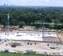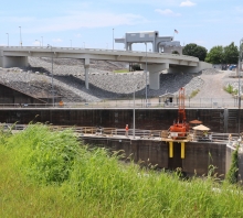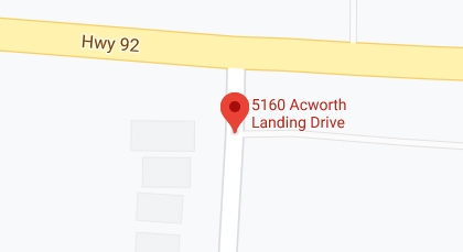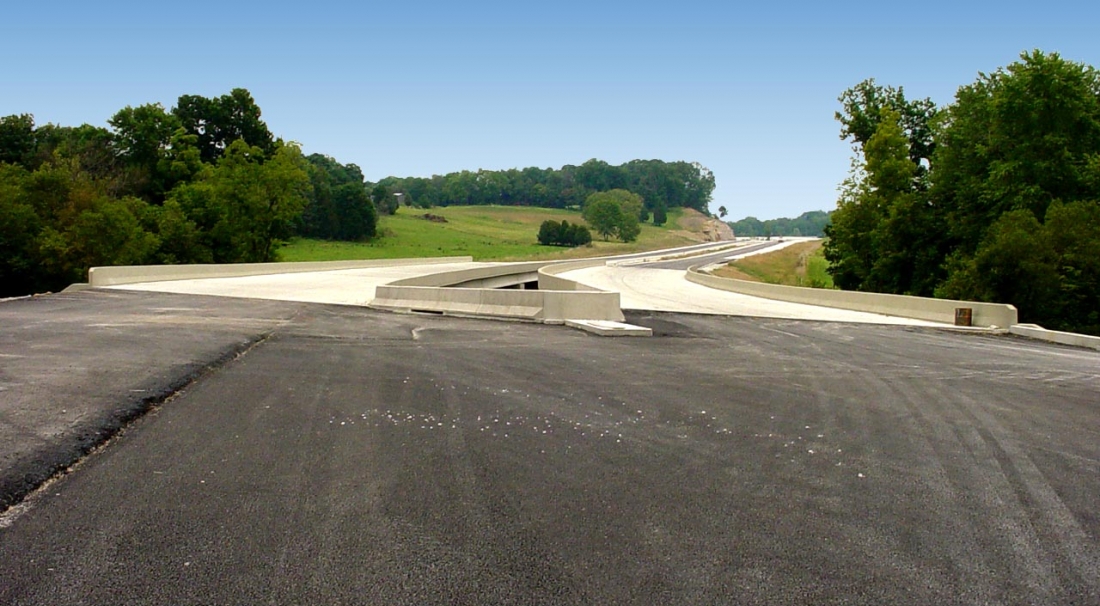

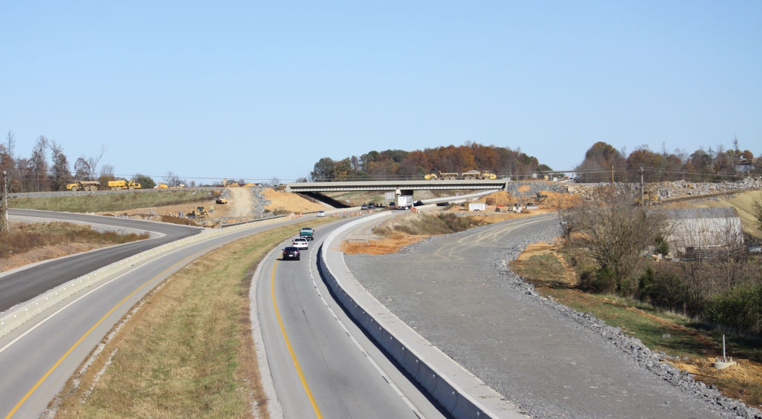
KY 3600 Glasgow Outer Loop, Design Sections 1,2,3, - over the South Fork of Beaver Creek is a dual two-span (112’-0” x 112’-0”) Type IV PCIB Bridge. It was determined that a two-span structure was more economical than the four-span alternate, despite “maxing out” the design on a Type IV PCI Beam. The Bridge is located in a vertical curve and has a 24° skew. One end of the bridge is supported on integral pile end bents driven to solid rock, while the central pier is composed of two stem walls founded on solid rock. Due to karst topography found in the area, the second end bent is founded on 4’ - 6” diameter steel-cased drilled shafts with rock sockets drilled into solid rock.
The Louie B. Nunn Parkway Bridge over Glasgow Outer Loop is a two-span (114’ x 114’) Type VI PCIB Bridge on an approximate 6° skew. The ends of the bridge are founded on pile-supported integral end bents and an intermediate pier supported on piles driven to rock. AEI completed the final design for the 4 and 5 span bridge over Beaver Creek from start to finish within six weeks!
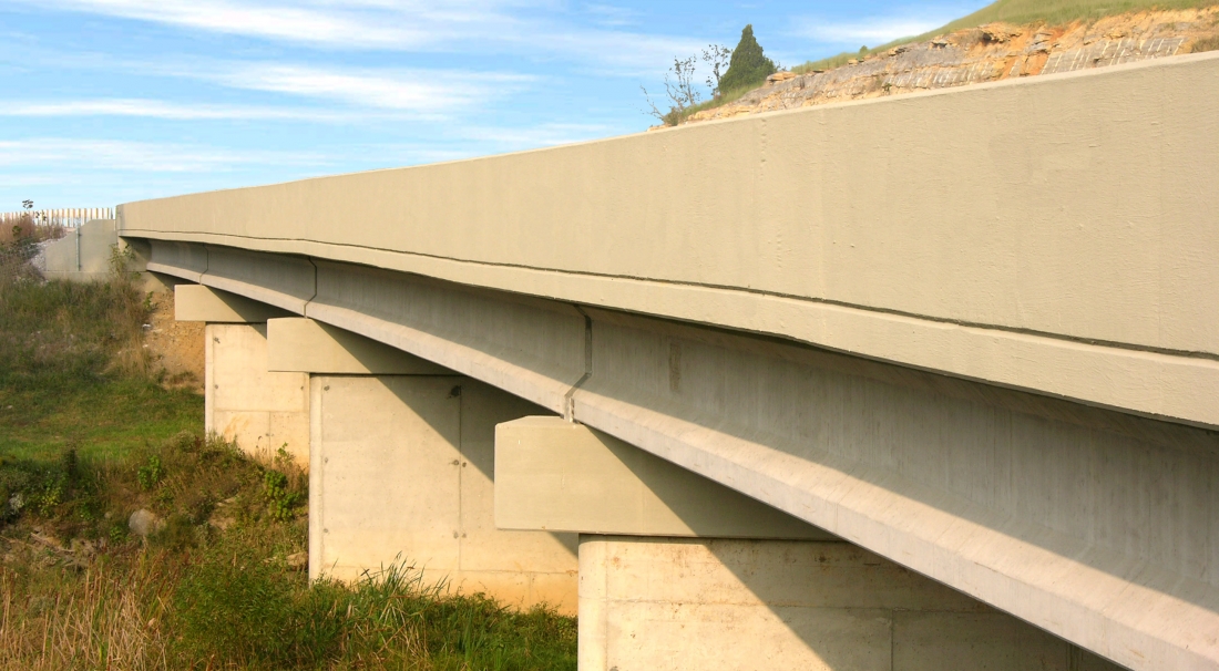
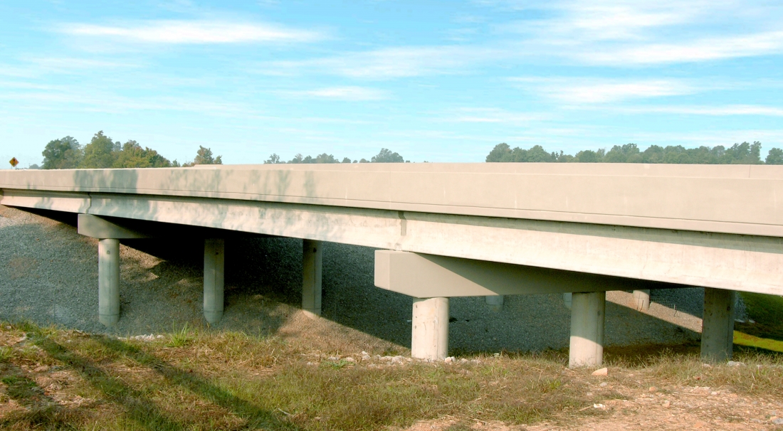
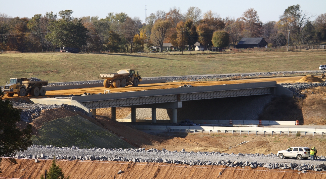
AEI also provided the structural design for two more bridges and four reinforced concrete box culverts on Glasgow Outer Loop Section 2, located in Barren County, Kentucky. Both bridges utilized prestressed concrete I-beams designed using the most current CON/SPAN software, and an 8” reinforced concrete deck with a standard New Jersey Barrier. Guardrail connections were specified at each corner of the bridges that continue onto the roadway portions of the projects.
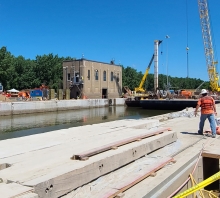
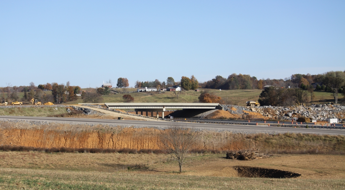
Additionally AEI designed , four 154’ – 473’ long reinforced concrete box culverts were designed to cross under Glasgow Outer Loop. . Culvert lengths were determined by geometry to allow for 2: 1 side slopes from the road shoulder. Culvert wing wall lengths were also designed to take into account the culvert skew and to allow the toe of the 2: 1 slope to wrap around the end of the wing and touch down at the barrel opening. Hydraulic analyses were performed using HY-8 and KTDID to ensure headwater elevations would not impact nearby homes or structures. The analyses dictated the opening and slopes of the culverts which varied from a 14’ x 5’ to a 20’ x 6’ opening. Large openings were used to prevent future maintenance issues including debris getting caught on interior walls and blocking flow. Each culvert was designed taking into account the overburden fill depth and bearing conditions (soil or rock). One culvert is founded on the non-yielding foundations (rock), which requires additional design strength due to the higher loads transmitted to the barrel top slab and side walls. Fill heights on the culverts ranged from 7’ to 54’ deep.